

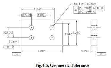
The function of geometric tolerance is to explain the engineering objective of components and assemblies. The datum reference frame can explain how the part. Tolerance can accurately define the dimensional needs for a part, permitting over 50% more tolerance than coordinate dimensioning in a few cases. Suitable purpose of tolerance will confirm that the part described on the drawing has the preferred form, fit and purpose with the highest possible tolerances (Fig.4.5).
1. Fundamental rules for Geometric Tolerance
All dimensions should have a tolerance. Each attribute on every manufactured component is subject to change; hence, the limits of acceptable difference must be defined. Plus and minus tolerances may be used to dimensions from a common tolerance block.
2. Dimensions describe the geometry and allowable change. Measurement and scaling of the drawing is not permitted excluding in certain cases.
3. Engineering drawings describe the necessities of completed parts. Each dimension and tolerance needed to define the completed part shall be shown on the drawing. If extra dimensions would be useful, but are not necessary, they may be noted as reference.
4. Dimensions should be used to attributes and arranged in such a way as to show the purpose of the features. In addition, dimensions should not be subject to more than one explanation.
5. Descriptions of manufacturing systems should be avoided. The geometry should be explained without defining the technique of manufacture.
6. If some sizes are needed during manufacturing but are not wanted in the final geometry they should be noticeable as non-mandatory.
7. All dimensioning and tolerance should be placed for utmost readability and should be used to visible lines in true profiles.
8. When geometry is usually restricted by code, the dimension(s) shall be integrated with code number in comments below the dimension.
9. If not openly declared, all dimensions and tolerances are only suitable when the item is in free.
10. Dimensions and tolerances indicate to the full length, width, and depth.
2. Tolerance Symbols
Symbols for tolerances are bilateral unless otherwise defined. For example, the location of a hole has a tolerance of .020mm. This indicates that the hole can move +/- .010 mm, which is an equal bilateral tolerance. It does not consider that the hole can move +.015/-.005 mm, which is an unequal bilateral tolerance. (Fig.4.6.).


