The mode of connection and the layout arrangement of the secondary arm of the divider is very critical for the distortion less measurement of fast transients. The L.V. arm of the divider itself introduces large distortions if not properly connected. Different corrections employed for connecting the L.V. arm to the measuring instrument via the signal cables are shown in Figs 7.38 and 7.39. The signal cable Z0 may be assumed to be loss-free so that the surge impedance, Z0 = √L/C is independent of the frequency and the travel time for the signal, T0 = √LC (refer to Chapter 8 for details).
In the case of resistance dividers, the cable matching is achieved by having a pure resistance, R2 = Z0at the end of the cable. The surge cable Z0 and the resistance R2 form an integral part of the cable system. Typically, Z0 has values of 50 or 75 ohms In actual practice, signal cables do have losses due to skin effect at high frequencies and hence; becomes a complex quantity. Thus, the matching of R2 with Z0 should be done at high frequencies or with a step input as indicated earlier.
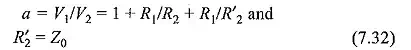
In the case of long cables, the cable resistance including that of the shield wire should be taken as a part of the matching resistance. The divider ratio in the case of the connection shown in Fig. 7.38 is
For the capacitance dividers, the signal cable cannot be completely matched. A low ohmic resistanceconnected in parallel with C2 would load the L.V. arm and hence, the output gets decreased. Connection of a resistance R= Z0 at the input end (see Figs 7.38 and 7.39) will make the voltage across the CRO the same as that across C2. The transient voltage ratio, at t = 0 is given as
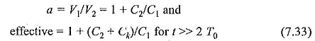
where Ck is the cable capacitance.
Thus, an initial overshoot of ΔV = Ck/(C1 + C2) will appear. This will be either small or negligible for medium and low cable lengths, and for high values of capacitance C2. This error can be avoided and the response improved in the
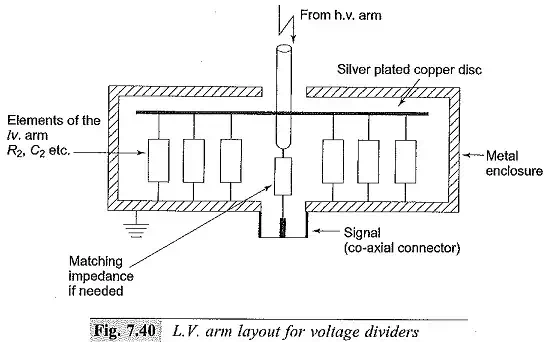
Usually, the L.V. arms are made co-axial and are enclosed in metal boxes that are solidly grounded. The series resistors used in R-C divider forms an integral part of the divider’s L.V. aim. Further, all the L.V. arm capacitors and resistors should have a very low inductance.