Elementary Circuits
1. Purely resistive circuit (R only)
The instantaneous value of the current though the circuit (Fig a) is given by,
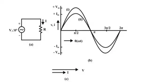
Circuit with Resistance (R) (a) circuit diagram (b) Waveforms (i)Voltage (ii) current (c) phasor diagram
The rms value of current is given by
Please note that the voltage and the current are in phase (φ = 0°), which can be observed from phasor diagram (Fig b) with two (voltage and current) phasors, and also from the two waveforms (Fig c).
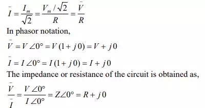
In ac circuit, the term, Impedance is defined as voltage/current, as is the resistance in dc circuit, following Ohm’s law. The impedance, Z is a complex quantity. It consists of real part as resistance R, and imaginary part as reactance X, which is zero, as there is no inductance/capacitance. All the components are taken as constant, having linear V-I characteristics. In the three cases being considered, including this one, the power consumed and also power factor in the circuits, are not taken up now, but will be described later in this lesson.
2. Purely inductive circuit (L only)
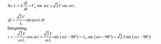
For the circuit (Fig a), the current i, is obtained by the procedure described here.
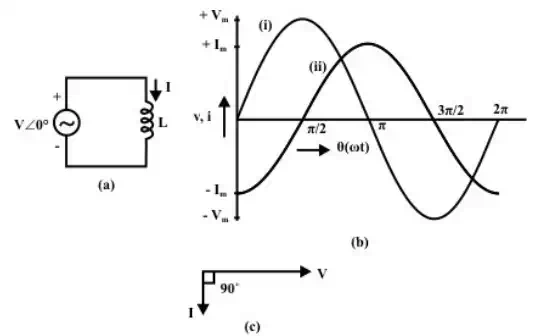
Circuit with Inductance (L)
(a) Circuit diagram
(b) Waveform (i) voltage (ii) current
(c) Phasor diagram
It may be mentioned here that the current i, is the steady state solution, neglecting the constant of integration. The rms value, I is
The impedance of the circuit is
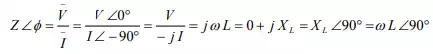

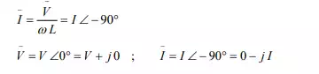
Note that the current lags the voltage by φ = +90°. This can be observed both from phasor diagram (Fig b), and waveforms (Fig c). As the circuit has no resistance, but only inductive reactance L = ω LX (positive, as per convention), the impedance Z is only in the y-axis (imaginary).
3. Purely capacitive circuit (C only)
The current i, in the circuit (Fig a), is,
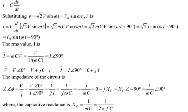
Note that the current leads the voltage by φ = 90° (this value is negative, i.e. φ 90°−= ), as per convention being followed here. This can be observed both from phasor diagram (Fig b), and waveforms (Fig c). As the circuit has no resistance, but only capacitive reactance, ![]() (negative, as per convention), the impedance Z is only in the y-axis (imaginary).
(negative, as per convention), the impedance Z is only in the y-axis (imaginary).
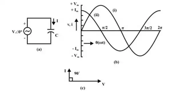
Circuit with capacitance (c)
(a) Circuit diagram
(b) Waveforms (i)voltage (ii) current
(c) Phasor diagram