Transient Single Phase Equivalent Circuit
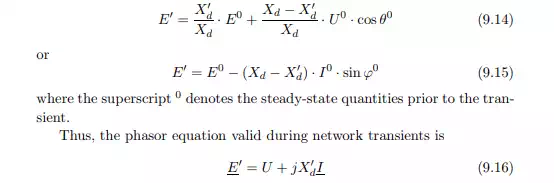
During network transients, the reactance of the synchronous generator is not constant. For symmetrical transients, as discussed in section 7.2 on short circuits of synchronous machines, the machine reactance itself undergoes transient changes as the machine passes through the sub-transient, transient, and steady-state stages. In the fault analysis in chapter 7, only the first few cycles after a fault were of interest. The generator was therefore modeled with the sub-transient reactance X′′ d . Compared to the time scale of short-circuit overcurrents, electro-mechanical oscillations are much slower (0.1 – 4 Hz as mentioned in the introduction to this chapter). For the study of these phenomena, the sub-transient phase is therefore neglected and the generator is modeled with the transient reactance X′ d . Similarly, during transients, the magnitude of the induced voltage drops to the value E′ which can be calculated as follows
Simplified Mechanical Model
An important parameter in the analysis of rotor oscillations is the total moment of inertia of the synchronous machine J. This is the sum of all moments of inertia of all rotating parts of the synchronous machine, i.e. the sum of the moments of inertia of the rotor, turbines, shafts and other devices on the shaft system, e.g. generator feeding the field winding. As for electrical quantities it is practical to express J in a suitable p.u. base and therefore the inertia constant of the synchronous machine H is defined as
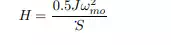
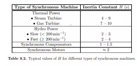
where S is the MVA rating of the machine. In eq. (9.18) the numerator is an expression for the total kinetic energy stored in the synchronous machine in steady state and the unit for H is thus seconds. (If there is a gear box in the system, it is of course difficult to define one mechanical angular velocity. In such a case H is calculated as the ratio between total stored kinetic energy and the MVA rating of the machine.) The inertia constant states how much time it would take to bring the machine from synchronous speed to standstill if rated power is extracted from it while no mechanical power is fed into it. The value of the inertia constant will vary within a much smaller range than the value of J for different machines. Table 9.2 shows typical values of H for different types of synchronous machines. It can be concluded that the value is higher for thermal units as compared with hydro units. Typically 30 – 60% of the total moment of inertia comes from the turbines and shafts for thermal units, while the corresponding value for hydro units is 5 – 15%. For synchronous motors the inertia constant depends to a high degree of what kind of load that is connected