Three types of magnetic fields — main fields or static fields (B2), gradient fields, an radiofrequency (RF) fields (B1) — are required in MRI scanners. In practice, it is also usually necessary to use coils or magnets that produce shimming fields to enhance the spatial uniformity of the static field B0. Most MRI hardware engineering is concerned with producing and controlling these various forms of magnetic fields. The ability to construct NMR instruments capable of examining test tube-sized samples has been available since shortly after World War II. The special challenge associated with the design and construction of medical scanners was to develop a practical means of scaling these devices up to sizes capable of safely and comfortably accommodating an entire human patient. Instruments capable of human scanning first became available in the late 1970s. The successful implementation of MRI requires a two-way flow of information between analog and digital formats (Figure 12.5). The main magnet, the gradient and RF coils, and the gradient and RF power supplies operate in the analog domain. The digital domain is centered on a general-purpose computer (Figure 12.6) that is used to provide control information (signal timing and amplitude) to the gradient and RF amplifiers, to process time-domain MRI signal data returning from the receiver, and to drive image display and storage systems. The computer also provides miscellaneous control functions, such as permitting the operator to control the position of the patient table.
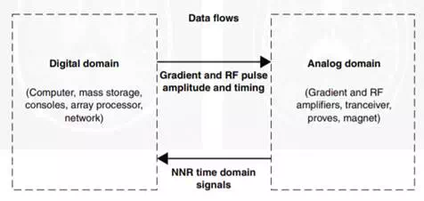
FIGURE 12.5 Digital and analog domains for MRI imaging. MRI involves the flow of data and system commands between these two domains (Courtesy of WM Leue. Reprinted with permission from Schenck and Leue, 1991)
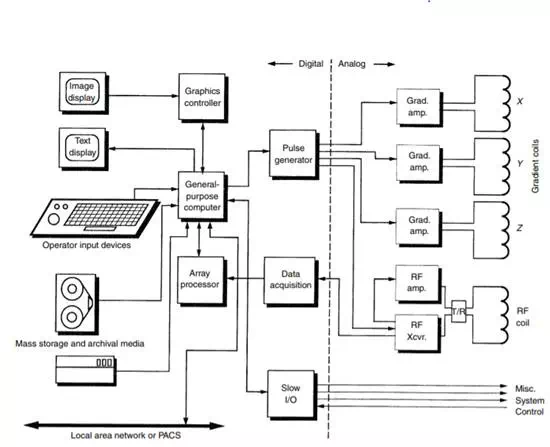
FIGURE 12.6 Block diagram for an MRI scanner. A general-purpose computer is used to generate the commands that control the pulse sequence and to process data during MR scanning. (Courtesy of WM Leue. Reprinted with permission from Schenck and Leue, 1991.)