Generation of Sinusoidal (AC) Voltage Waveform

Prabhu TL
1 Min Read
Disclosure: This website may contain affiliate links, which means I may earn a commission if you click on the link and make a purchase. I only recommend products or services that I personally use and believe will add value to my readers. Your support is appreciated!

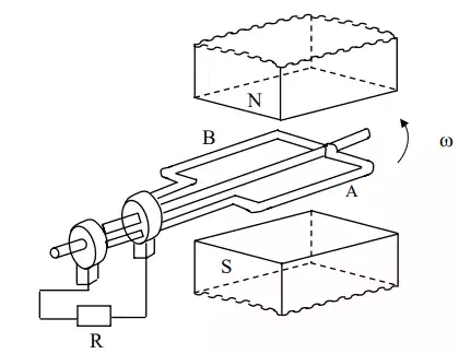
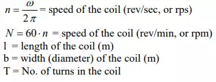
Schematic diagram for single phase ac generation

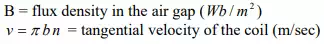
A multi-turn coil is placed inside a magnet with an air gap as shown in Fig. above. The flux lines are from North Pole to South Pole. The coil is rotated at an angular speed, ω = 2π n (rad/s).

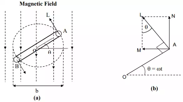
At a certain instant t, the coil is an angle (rad), θ = ωt with the horizontal (Fig. 12.2).

The emf (V) induced on one side of the coil (conductor) is Blv sinθ , θ can also be termed as angular displacement.

The emf induced in the coil (single turn) is 2Blvsin θ = 2 Bl π bsinθ.

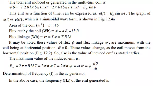
The total emf induced or generated in the multi-turn coil is e(θ) = T2Bl π bsinθ = 2 π BlbnT sinθ.

Share This Article
Prabhu TL is a SenseCentral contributor covering digital products, entrepreneurship, and scalable online business systems. He focuses on turning ideas into repeatable processes—validation, positioning, marketing, and execution. His writing is known for simple frameworks, clear checklists, and real-world examples. When he’s not writing, he’s usually building new digital assets and experimenting with growth channels.
Leave a review