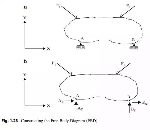
Generating an idealization of an actual structure is the key step in applying the equilibrium equations. Given a structure acted upon by external loads and constrained against motion by supports, one idealizes the structure by identifying the external loads and supports, and replacing the supports with their corresponding unknown reaction forces. This process is called constructing the free body diagram (FBD). Figures 1.23a, b illustrate the details involved.
One applies the equilibrium equations to the FBD. Note that this diagram has 4 unknown reaction forces. Since there are only three equilibrium equations, one cannot determine all the reaction forces using only the equilibrium conditions. In this case, we say that the structure is statically indeterminate.
Constructing a FBD is an essential step in applying the equilibrium equations. The process is particularly useful when the structure is actually a collection of interconnected structural components such as a framed structure. One first generates a FBD for the entire structure and then works with separate FBD’s for the individual members. We illustrate this approach throughout the text.
Internal Forces
Consider the body shown in Fig. 1.24a. Suppose we pass a cutting plane as indicated and separate the two segments. We represent the action of body “n” on
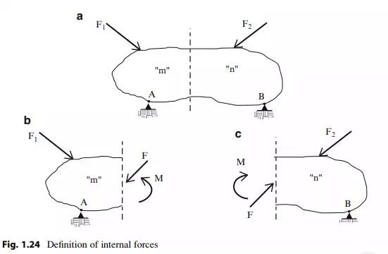
body “m” by a force F ! and moment M !. From Newton’s third law, the action of body m on body n is opposite in sense. Once the reaction forces are known, we can determine F ! and M ! by applying the equilibrium conditions to either segment. These force quantities are called “internal forces” in contrast to the reactions which are “external forces.” Note that the magnitude of the internal forces varies with the location of the cutting plane. The following example illustrates the process of computing internal forces.