Schmitt trigger is an electronic circuit with positive feedback which holds the output level till the input signal to comparator is higher than the threshold.It converts a sinusoidal or any analog signal to digital signal. It exhibits hysteresis by which the output transition from high to low and low to high will occur at different thresholds.
Principle of operation
Consider a feedback system with forward gain of A and feedback factor β. If we adjust the loop gain to be one then the gain with feedback becomes infinite. This results in ever ending transition of output between extremes of output. Schmitt trigger is one of such regenerative circuits also called as astable multivibrator because of two quasi stable (unstable) states which are 1.positive extreme and 2.negative extreme.
Circuit diagram
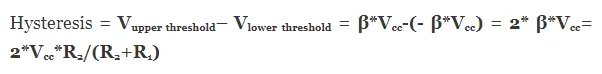
The opamp Schmitt trigger is as shown below
It is obvious from the circuit that positive feedback is employed in the circuit. The feedback factor
β =Vf / Vo = R2/(R2+R1).
Circuit analysis
From the figure shown above the let us assume a sinusoidal voltage is applied and at first output is in positive saturation state. Then the feedback voltage Vf = β*Vcc. Now when input Vin falls below β*Vcc then the voltage at inverting terminal is greater than the voltage at non inverting terminal, so the output will be positive and is equal to –Vcc. This value of input voltage at which output makes transition from positive saturation voltage to negative saturation voltage is called upper threshold.
At this point Vf = -β*Vcc now if input is allowed to fall below -β*Vcc then the voltage at non inverting terminal is greater than the voltage at inverting terminal, so the output makes transition from–Vcc to + Vcc. This value of input voltage at which output makes transition from negative saturation voltage to positive saturation voltage is called lower threshold.This process continues till sine wave input exists at input and DC power supply for opamp is on. Below is a diagram showing the input and output characteristics of opamp schmitt trigger
Hysteresis
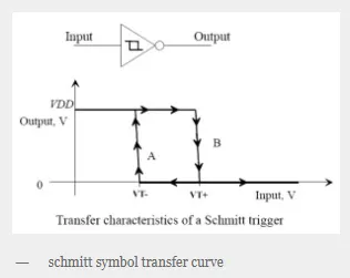
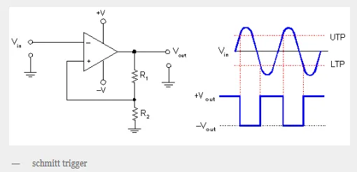
The transfer characteristics of schmitt trigger is shown in the figure along with the symbol. The phenomenon by which the circuit triggers at a higher voltage for increasing voltages than for decreasing voltages is called hysteresis. Because of hysteresis there exists two triggering voltage i.e. upper threshold and lower threshold for Schmitt trigger. It is quantified as follows