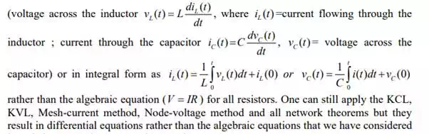
So far we have considered dc resistive network in which currents and voltages were independent of time. More specifically, Voltage (cause → input) and current (effect → output) responses displayed simultaneously except for a constant multiplicative factor R (V= R × I). Two basic passive elements namely, inductor ( L ) and capacitor (C ) are introduced in the dc network.. The voltage/current relationship for these two passive elements are defined by the derivative,
in resistive networks.
An electric switch is turned on or off in some circuit (for example in a circuit consisting of resistance and inductance), transient currents or voltages (quickly changing current or voltage) will occur for a short period after these switching actions. After the transient has ended, the current or voltage in question returns to its steady state situation (or normal steady value). Duration of transient phenomena are over after only a few micro or milliseconds, or few seconds or more depending on the values of circuit parameters (like R, , L and C ).The situation relating to the sudden application of dc voltage to circuits possessing resistance ( R ), inductance ( L ), and capacitance (C ) will now be investigated in this lesson. We will continue our discussion on transients occurring in a dc circuit. It is needless to mention that transients also occur in ac circuit, but they are not included in this lesson.
Significance of Inductance of a coil and dc transients in a simple R-L circuit
Fig.10.1 shows a coil of wire forming an inductance and its behaviour is to resist any change of electric current through the coil. When an inductor carries current, it produces a certain amount of magnetic flux (Φ ) in the core or space around it. The product of the magnetic flux (Φ ) and the number of turns of a coil (an inductor) is called the ‘flux linkage’ of the coil.
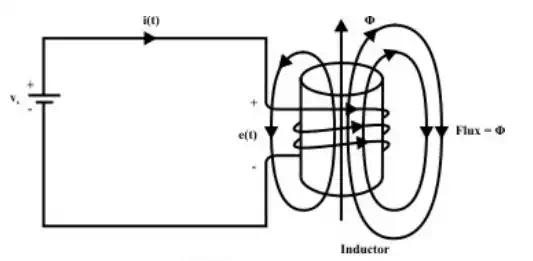
Considering the physical fact that the voltage across the coil is directly proportional to the rate of change of current through the inductor and it is expressed by the equation.
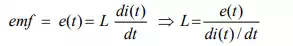
In words, Faraday’s law states that the voltage induced in a coil (inductor) is proportional to the number of turns that the coil has, and also to the rate of change of the magnetic flux passing through its coils. From equations, one can write the following relation
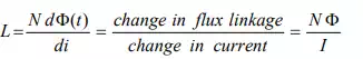
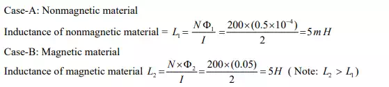
The inductance of a coil can also be defined as flux (Φ ) linkage per unit of current flowing through the coil and it is illustrated through numerical example.
Example
Consider two coils having the same number of turns ‘ ’. One coil is wrapped in a nonmagnetic core (say, air) and the other is placed on a core of magnetic material as shown in fig. Calculate the inductances of both coils for same amount of current flowing through them.
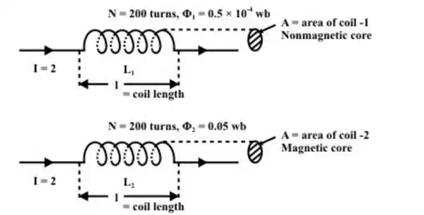
Inductance of coil depends on the surrounding media