The two-wire ac circuits shown above (called single-phase circuits or systems), are commonly used in residential, commercial, and low voltage—low power industrial applications. However, all electric power systems to which industrial generators are connected are three-phase systems. Therefore any discussion in this book about the “power system” will refer to a three-phase system. Moreover in industrial applications the voltage supplies are, for all practical reasons, balanced, meaning all three-phase voltages are equal in magnitude and apart by 120 electrical degrees.
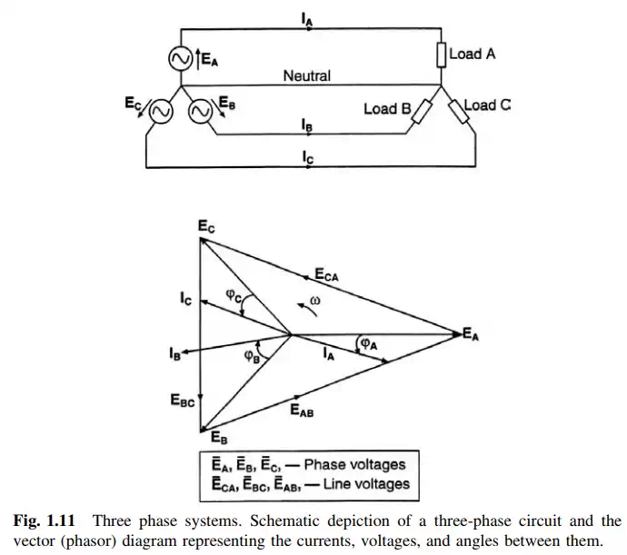
Three-phase electric systems may have a fourth wire, called “neutral.” The “neutral” wire of a three-phase system will conduct electricity if the source and/or the load are unbalanced. In three-phase systems two sets of voltages and currents can be identified. These are the phase and line voltages and currents.
Figure 1.11 shows the main elements of a three-phase circuit. Three-phase circuits can have their sources and/or loads connected in wye (star) or in delta.
Almost without exception, turbine-driven generators have their windings connected in wye (star). Therefore in this book the source (or generator) will be shown wye-connected. There are a number of important reasons why turbogenerators are star-connected. They have to do with considerations about its effective protection as well as design (insulation, grounding, etc.). These will be discussed in the chapters covering stator construction, and operations.
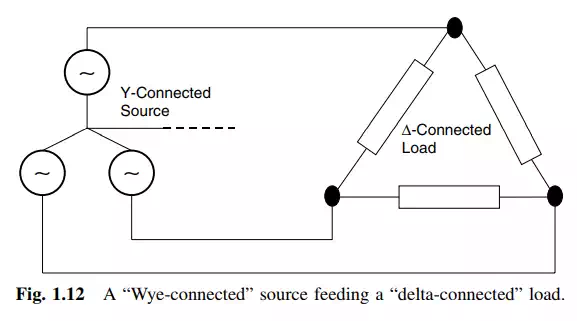
On the other hand, loads can be found connected in star, delta, or a combination of the two. This book is not about circuit solutions; therefore the type of load connection will not be brought up herein.
Faraday’s Law of Electromagnetic Induction
This basic law, due to the genius of the great English chemist and physicist Michael Faraday (1791–1867), presents itself in two different forms:
1. A moving conductor cutting the lines of force (flux) of a constant magnetic field has a voltage induced in it.
2. A changing magnetic flux inside a loop made from a conductor material will induce a voltage in the loop.
In both instances the rate of change is the critical determinant of the resulting differential of potential. Figure 1.13 illustrates both cases of electromagnetic induction, and also provides the basic relationship between the changing flux and the voltage induced in the loop, for the first case, and the relationship between the induced voltage in a wire moving across a constant field, for the second case. The figure also shows one of the simple rules that can be used to determine the direction of the induced voltage in the moving conductor.