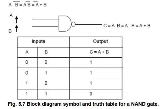
A NAND gate is a complemented AND gate. That is the output of NAND gate will be 1 if any one the input is 0, and it will be 0 only when all inputs are 1.
Below Figure 5.7 shows the truth table and block diagram symbol for a NAND gate. The symbol ‘ ‘ is usually used to represent a NAND operation in Boolean expressions.
Hence
An AND gate followed by a NOT gate operates as a NAND gate (see Figure above) . In the figure, the output of the AND gate will be A .B that is turn is fed as input to the NOT gate. Hence, the final output will be complement of A.B, which is equal to (A.B) or A + B or A B. in fact, the small circle on the output of NAND gate (see Figure 6.24) represents complementation.
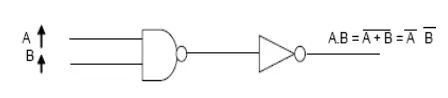
Figure 5.8 Demonstrating NAND gate realization with AND gate and a NOT gate
Multiple-input NAND gates can be analyzed similarly. A three-input NAND gate with inputs, A,B, and C will have output equal to A.B.C or A + B + C meaning that the output will be 1 if any of the inputs is a 0, and it will be 0 only when all three inputs are 1.