Complex trusses are defined as truss structures that cannot be classified as either simple or compound trusses. In order to determine the member forces, one has to establish the complete set of nodal force equilibrium equations expressed in terms of the member forces. If the truss is statically determinate, the number of equations will be equal to the number of force unknowns, and theoretically one can solve these equations for the force unknowns. However, if one cannot determine the member forces, the truss is said to be geometrically unstable. Static determinacy is a necessary but not sufficient condition for stability. In what follows, we expand on this point.
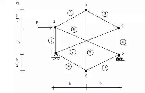
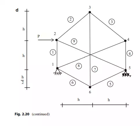
Consider the planar truss shown in Fig. 2.20a. There are nine members, three reactions, and six nodes. Then,
and the truss is statically determinate. It also has a sufficient number of reactions to prevent rigid body motions.
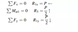
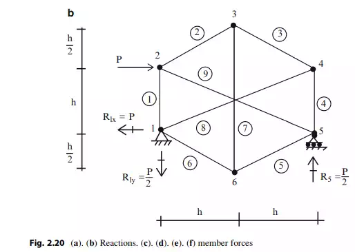
We use 3 of the 12 equilibrium equations to determine the reactions, leaving 9 equations available to solve for the 9 member forces.
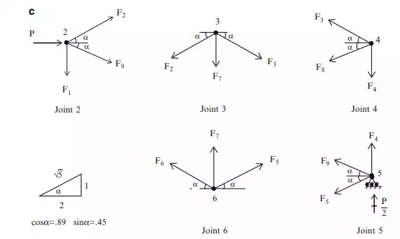
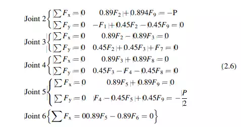
Enforcing equilibrium at joints 2–6 results in the following nine equations:
We express (2.6) in matrix form
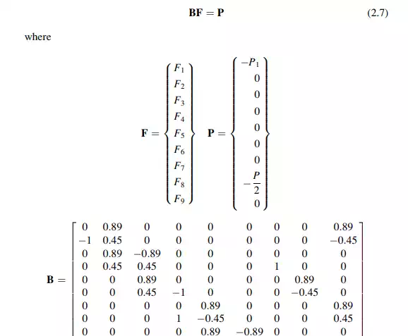
The coefficient matrix, B is singular (the determinate of B equals 0). Therefore, a unique solution for the unknown forces does not exist for an arbitrary nodal load.
The truss is said to be geometrically unstable since the elements of B depend only on the geometric pattern.
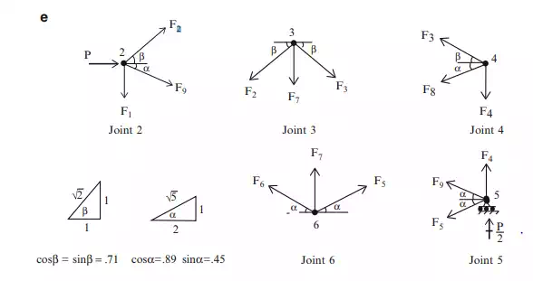
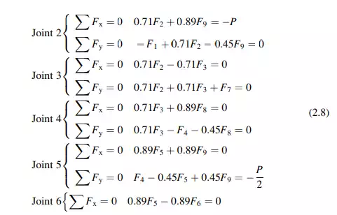
In order to eliminate the instability, one needs to change the geometry. We modify the truss by changing the vertical position of node 3 as shown in Fig. 2.20d. The individual nodal force systems are defined in Fig. 2.20e and the corresponding nodal force equilibrium equations are listed in (2.8).
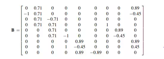
In this case, the coefficient matrix B is nonsingular (detB 6¼ 0), and it follows that the structure is geometrically stable:
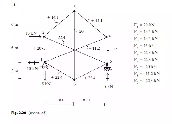
Solving (2.8) using a computer software system [30] leads to member forces listed below.
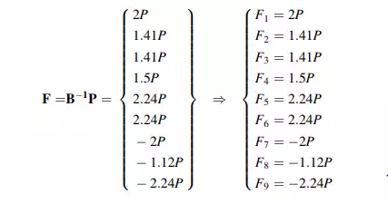
For P ¼ 10 kN and h ¼ 6 m, the member forces are listed in Fig. 2.20f.
Assembling the nodal force equilibrium equations usually is a tedious operation, especially for three-dimensional space structures. The process can be automated by using matrix operations.