Valve positioners are used to control the valve actuator position of the control valve. The positioner receives the signal from the controller and correct position by increasing or decreasing the air load pressure on the actuator.
Signal conversion:
A 3 to 15 PSIG pneumatic signal would be sent from the loop device in the control chamber to the field valve prior to 4 to 20 mA digital command.
This signal sents to the positioned mounted on the valve. The positioner would compare the valve stem or shaft position with the loop controller’s 3 to 15 PSIG signal and output the correct pressure to the valve actuator to position the valve at the exact location defined by the loop controller’s 3 to 15 PSIG signal.
Control Valve connection
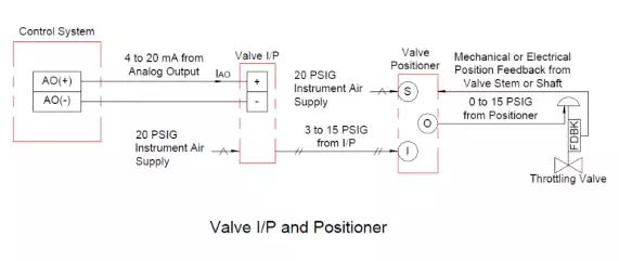
4 to 20 mA signal is sent to the current-to-pressure (I/P) converter from the loop controller, which then displays a 3 to 15 PSIG signal to the positioner mounted on the valve, which operates as described above.
Some positioner designs have built-in I/Ps (also known as electro-pneumatic positioners). Some production facilities favour mounting the I/Ps remotely from the valve owing to vibration, temperature, crop norms, or some other issue.