This design example, identified by the arrow icon, will be considered sequentially in each chapter. We will use the design process of Figure 1.22 in each chapter to identify the steps that we are accomplishing. For example, in Chapter 1 we are concerned with steps 1, 2, 3, and 4, where we (1) identify the control goal, (2) identify the variables to control, (3) write the initial specifications for the variables, and (4) establish the preliminary system configuration.
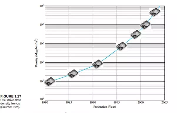
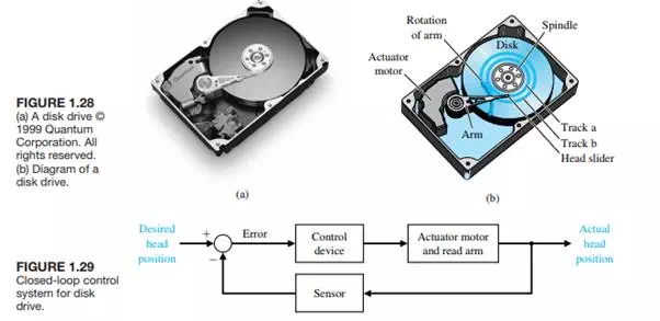
Information can be readily and efficiently stored on magnetic disks. Disk drives are used in notebook computers and larger computers of all sizes and are essentially all standardized as defined by ANSI standards [54, 69]. Worldwide sales of disk drives are estimated to be greater than 250 million units in 2002 [55, 68]. In the past, disk drive designers have concentrated on increasing data density and data access times. In fact, beginning in the early 1990s, disk drive densities increased at rates of over 60 percent per year and very recently, these rates exceed 100 percent per year. Figure 1.27 shows the disk drive density trends. Designers are now considering employing disk drives to perform tasks historically delegated to central processing units (CPUs), thereby leading to improvements in the computing environment [69]. Three areas of “intelligence” under investigation include off-line error recovery, disk drive failure warnings, and storing data across multiple disk drives. Consider the basic diagram of a disk drive shown in Fig. 1.28. The goal of the disk drive reader device is to position the reader head in order to read the data stored on a track on the disk (step 1). The variable to accurately control (step 2) is the position of the reader head (mounted on a slider device). The disk rotates at a speed between 1800 and 7200 rpm, and the head “flies” above the disk at a distance of less than 100 nm .
The initial specification for the position accuracy is (step 3). Furthermore, we plan to be able to move the head from track a to track b within 50 ms, if possible. Thus, we establish an initial system configuration as shown in Figure 1.29. This proposed closed-loop system uses a motor to actuate (move) the arm to the desired location on the disk.