Skip to content
Tue, Oct 13, 2026 / Ideas for a clearer worldINDEPENDENT INSIGHTS · PRACTICAL TOOLS · EXPLAINERS
Sign in
Design of Machine Elements / July 17, 2021

Turning Moment Diagram for a Multi-cylinder Engine

A separate turning moment diagram for a compound steam engine having three cylinders and the resultant turning moment diagram is shown in Fig. 16.3. The resultant turning moment diagram is the sum of the turning moment diagrams for the three cylinders. It may be noted that the first cylinder is the high pressure cylinder, second […]

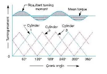
A separate turning moment diagram for a compound steam engine having three cylinders and the resultant turning moment diagram is shown in Fig. 16.3. The resultant turning moment diagram is the sum of the turning moment diagrams for the three cylinders. It may be noted that the first cylinder is the high pressure cylinder, second cylinder is the intermediate cylinder and the third cylinder is the low pressure cylinder. The cranks, in case of three cylinders, are usually placed at 120° to each other.